
What is Electromagnetic Interference?
Electromagnetic interference (EMI) is the electronic noise that interferes with the cable signal and reduces the integrity of the signal. EMI is usually generated by electromagnetic radiation sources such as motors and machines.
Types of Electromagnetic Interference
From the interference source, electromagnetic interference can be divided into natural interference source and man-made interference source. Natural sources of interference include electrical noise from thunderstorms and lightning everywhere on Earth, noise from sunspot explosions and activity, and cosmic noise from the Milky Way GALAXY. Man-made interference source is the electromagnetic interference produced by mechanical and electrical or other artificial devices, it includes: all kinds of radio transmitter; industrial, scientific and medical radiofrequency equipment; overhead transmission lines, high-voltage equipment and electric traction systems; Electromechanical vehicles and internal combustion engines; electric motors, household appliances, lighting appliances and similar equipment; information technology equipment; as well as electrostatic discharge and electromagnetic pulse. With the development of science and technology and productive forces and the improvement of people’s living standards, the types of man-made interference sources are increasing, and the electromagnetic interference generated is becoming more and more serious in polluting the environment. At present, man-made interference has become the main source of electromagnetic environmental levels.
Electromagnetic interference can be divided into conducted interference and radiated interference from the transmission route of interference. Electromagnetic interference transmitted along a wire is called conducted interference. There are various connections between the devices in an electronic system or between the unit circuits in an electronic device, so that the electromagnetic energy of one device (or unit circuit) may be transmitted along such wires to other devices and unit circuits, thus causing interference. Radiated interference refers to electromagnetic interference that propagates through space. Wires such as circuit of interference source, input and output signal circuit and control circuit can form radiating antenna or receiving antenna under certain conditions. If the shell of the interference source flows through the high-frequency current, the shell itself also becomes the radiation antenna or the receiving antenna.
According to the effect of electromagnetic interference, electromagnetic interference includes two aspects: internal interference and inter-system interference.
Three Elements of Electromagnetic Interference
1. Electromagnetic interference source
Electromagnetic interference sources include microprocessors, microcontrollers, transmitters, electrostatic discharge and instantaneous power components, such as electromechanical relays, switching power supplies, lightning, etc. In a microcontroller system, the clock circuit is the largest broadband noise generator, and this noise is diffused throughout the spectrum. With the development of a large number of high-speed semiconductor devices, their edge hopping rates are very fast and such circuits will generate harmonic interference up to 300 MHz.
2. Coupling paths
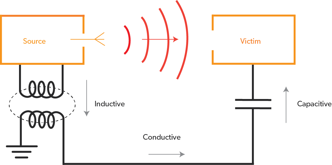
The noise is coupled to the conductor in the circuit that is most easily passed through, as shown in the figure for analyzing the EMI mechanism. If a wire passes through a noisy environment, the wire senses the ambient noise and transmits it to the rest of the circuit. Noise enters the system through the power line, and the noise carried by the power line is transmitted to the whole circuit, which is a coupled situation.
Coupling also occurs in circuits with a shared load (impedance). For example, two circuits share a power supply wire or a ground wire. If one circuit needs a burst of large current, and the two circuits share the power line, equivalent to access the same internal resistance of the power supply, the current imbalance will cause the supply voltage of the other circuit to drop. The effect of this coupling can be reduced by reducing the common impedance. But the internal resistance of the power supply and the grounding wire are fixed. If the ground is unstable, the return current flowing in one circuit will produce a change in the ground potential in the ground loop of the other circuit, and the change in ground potential will seriously reduce the performance of low-level analog circuits such as analog/digital converters, operational amplifiers, and sensors.
In addition, electromagnetic radiation is present in each circuit, which forms the coupling between the circuits. When the current is changed, electromagnetic waves are produced. These waves can couple to nearby conductors and interfere with other signals in the circuit.
3. Receiver
All electronic circuits are subject to electromagnetic interference. Although a portion of EMI is directly received in the form of radiofrequency radiation, the majority of EMI is received by instantaneous conduction. In digital circuits, critical signals such as reset, interrupt and control signals are most susceptible to electromagnetic interference. Control circuits, analog low-level amplifiers, and power adjustment circuits are also susceptible to noise.
Principle of Electromagnetic Interference
Analysis of electronic circuits and electromagnetic interference
Modern electronic products are becoming more and more powerful, electronic circuits are becoming more and more complex, electromagnetic interference (EMI) and electromagnetic compatibility problems have become major problems, and circuit design requires more and more technical level of designers. Electromagnetic interference is generally divided into two types, conducted interference and radiated interference. Conducted interference refers to the coupling (interference) of signals on one electrical network to another electrical network through a conductive medium. Radiated interference is when an interference source couples (interferes) its signal to another electrical network through space. Therefore, the study of emc problems is the study of the relationship between interference sources, coupling pathways, and sensitive devices.
The Federal Communications Commission (FCC) introduced regulations for commercial digital products in 1990 and the European Union (EU) in 1992, requiring companies to ensure that their products meet strict magnetization coefficient and emission guidelines. Products that comply with these regulations are called electromagnetic compatibility.
At present, emc corresponding market access certifications have been basically set up in all regions of the world to protect the electromagnetic environment and the competitive advantages of local products in the region. For example, FCC certification in North America, NEBC certification, CE certification in the European Union, VCCEI certification in Japan, C-TIck certificate in Australia, BSMI certification in Taiwan, 3C certification in China, etc. are all “passes” to enter these markets.
Electromagnetic induction and electromagnetic interference
When many people are engaged in electronic circuit design, they start from understanding electronic components, but engaging in electromagnetic compatibility design should actually start from electromagnetic field theory, that is, starting from electromagnetic induction understanding.
General electronic circuits are composed of resistors, capacitors, inductors, transformers, active devices and wires, when there is a voltage in the circuit, an electric field will be generated around all the charged components, when there is a current flowing through the circuit, there is a magnetic field around all the carrier fluid.
The capacitor is the most concentrated component of the electric field, the current flowing through the capacitor is the displacement current, this displacement current is due to the two plates of the capacitor are charged, and an electric field is generated between the two plates, through the electric field induction, the two plates will produce charge and discharge, forming a displacement current. In fact, the current in the capacitor loop does not really flow through the capacitor, but only charges and discharges the capacitor. When the two plates of the capacitor are opened, the two plates can be regarded as a set of electric field radiation antennas, and the circuit between the two plates will induce the electric field between the plates. The circuit between the bipolar plates, whether closed loops or open circuits, generates a displacement current in a conductor consistent with the direction of the electric field (when the direction of the electric field is constantly changing), that is, the current runs forward for a while and backward for a while.
The electric field strength is defined as a potential gradient, that is, the ratio of the potential difference to the distance between two points. A wire several meters long, when it flows through several amperes of current, the voltage at both ends is only a few tenths of a few volts at most, that is, the strength of the electric field of tens of millivolts / meter, everal amperes of current is generated in the conductor, which shows the great effect of the electric field and the strong interference ability.
Inductors and transformers are the components with the most concentrated magnetic field, and the current flowing through the secondary coil of the transformer is the induced current, which is generated because there is a current in the primary coil of the transformer that flows through the time and generates magnetic induction. The circuit around the inductor and transformer can be regarded as the induction coil of a transformer, and when the magnetic field line generated by the inductor and the transformer leakage sense passes through a circuit, the circuit as the “secondary coil” of the transformer will generate an induced current. The circuit of two adjacent circuits can also be regarded as the “primary coil” of the transformer, while the other circuit can be regarded as the “secondary coil” of the transformer, so the two adjacent circuits also produce electromagnetic induction, that is, interference with each other.
Electromagnetic interference occurs as long as there is an electric or magnetic field in the electronic circuit. In high-speed PCB and system design, high-frequency signal lines, integrated circuit pins, various connectors, etc. may become radiated interference sources with antenna characteristics, which can emit electromagnetic waves and affect the normal operation of other systems or other subsystems in the system.
Hazards of Electromagnetic Interference
(1) The harm to electronic systems and equipment
Strong electromagnetic interference can cause sensitive electronic equipment to be damaged by overload. In general, the reverse breakdown voltage between the emitter and the base electrode of the silicon transistor is 2 to 5V, which is very easy to damage, and its reverse breakdown voltage decreases with increasing temperature. Voltage spikes caused by electromagnetic interference can increase the concentration of impurities at a point in the emission and collector junctions, causing transistor breakdown or internal short circuits. Transistors operating under strong RF electromagnetic fields absorb enough energy to cause damage due to junction temperatures that exceed the allowable temperature rise.
(2) The harm to weapons and equipment
Modern radio transmitters and radars can produce a strong electromagnetic radiation field. This radiation field can cause sensitive electronic detonation devices installed in weapons and equipment systems to be started prematurely out of control; The misalignment of the guided missile will lead to deviation from the flight trajectory and increase the distance error; For aircraft, it will cause operating system instability, inaccurate heading, altitude display errors, radar antenna tracking position shifts, etc.
(3) The harm to the human body Once electromagnetic radiation enters human cell tissue, it will cause biological effects, that is, local thermal effects and non-thermal effects. The mechanism of non-thermal effects is more complex and needs to be further explored. The thermal effect depends on the radiated peak power, but is also related to the frequency. Thermal effects are most severe in the range of 1 to 3 GHz, and the energy absorbed by biological effects can reach 20% to 100% of the incident energy. In other frequency ranges, biological effects absorb about 40% of the incident energy. The degree of harm to the human body from different frequencies of electromagnetic radiation is not the same. For radiation below 1GHz, the skin tissue is sluggish, the energy permeability is strong, and it is easy to cause deep tissue heat and damage. For radiation from 1 to 3 GHz, the surface tissues and deep tissues of the human body will absorb energy, such as the eyeball and internal tissues are easily damaged. The thermal effect of electromagnetic fields can increase the temperature of the human body, and when the human body exceeds the normal body temperature, the metabolism and oxygen requirements quickly increase, such as the temperature rises.
